This article attempts to explain how astronomy filters are designed to work at different focal ratios, while preserving their target wavelength as best as possible.
How do Dichroic Light pollution filters work? Dichroic filters work by internally reflecting light between layers of metal closely deposited on glass. The spacing between the layers determines the wavelength of light passed by the filter, and also the wavelength blocked by the filter. Most filters are targeted at specific wavelengths emitted by nebulae, while blocking light emitted by street lamps and other unwanted sources. These are predominantly the ionized Oxygen “Oiii” and Hydrogen “Ha” emission lines, though other wavelengths can be included.
Target Central Wavelength (CWL): The target wavelength (also known as the Central Wave Length or “CWL”) is quoted by astronomy filter manufacturers. Filters attempt to pass as much of the target wavelengths through, while significantly blocking unwanted wavelengths, such as sky-glow or light pollution. An efficient a filter blocks as much unwanted light as possible to increase the contrast between the target wavelength and the background. The two most common targets for a filter’s CWL are those emitted by emission nebulae – for example Oxygen Oiii (500.7nm), and Hydrogen Alpha Ha (656.28 nm).
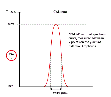
Full Width at Half Maximum (FWHM): Filter manufacturers quote a FWHM number such as 3nm, 7nm or 15nm, and so-on. FWHM stands for “Full Width at Half Maximum”. This is the “width of frequency range, where less than half the signal’s power is attenuated”, i.e., the signal power is at least half the maximum or 50%. The FWHM number gives an idea of the performance of a filter, amongst other factors. It’s often referred to as the filter “passband” or “bandpass.”
Blue shift, F-Ratio and filter angle of incidence: If light strikes a filter at an angle from the perpendicular, the distance a beam of light has to travel between the dichroic layers will change, causing the transmitted wavelength frequency to change.
Telescope optics which pass light with a “fast” focal ratio through a filter cause the light rays to strike the filter at a greater angle. Therefore, as the focal ratio of the optics gets faster (F-Ratio number decreases towards 0), the passband of a filter starts to shift towards the blue end of the spectrum.
The amount of blue shift is relative to the angle of light rays striking the filter, and it can be modelled. For example, at a focal ratio of F1.9, the angle of incidence (or “AOI” of the light cone is 15°, causing a shift towards the blue end of the spectrum of about 6nm. At F4.0, the AOI is only about 7°, and most filters will perform well at F4.0 or higher.
In general, when the passband is significantly shifted towards the blue, away from the target CWL, the effect is that the apparent brightness of the most desirable transmitted light decreases. This can cause reduced contrast between a nebula and the background sky.
For reasons beyond the scope of this article, the wavelengths most affected by a change in AOI tend to be the longer ones in the red regions of the spectrum – usually Hydrogen Alpha Ha and Sulphur Sii emission lines. Oiii and HBeta at the blue end of the spectrum tend not to be affected as much due to their shorter wavelength.
Filter manufacturers generally employ three main strategies, or a combination of them, to deal with fast focal ratios:
Here’s a quick summary of the pros and cons of each technique:
| Strategy: | How does it work? | Pros | Cons | Passband and recommended f-ratio. |
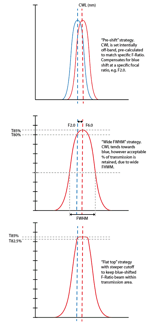
| #1 Use a wider passband | By encompassing the target central wavelength and areas either side of it. | Very tolerant of fast focal ratios. Usually very good transmission on-target. Less expensive. | Some “leakage” of other light sources. May not be as effective in extreme light pollution. | Usually 10nm, or wider. Up to F1.8. |
| #2 “Flat top” passband | The passband peak is “squared off” and the sides are as steep as possible, making the peak transmission extend either side of the CWL, but within the stated FWHM. This tries to keep transmission high, even though blue shifted. | Passes the target bandpass very efficiently at normal focal ratios. Extremely high contrast at commonly used focal ratios. Quite tolerant of faster focal ratios (until the angle becomes too extreme). | When the focal ratio angle passes a certain point, the % transmission at the target CWL will start to fall off rapidly, especially at very fast focal ratios. Expensive to manufacture. | Generally less than 10nm, and more in the 7nm region. Falloff starts at about F2.0. |
| # Blue-shifted passband. | Keeping the narrow bandpass as it is in terms of FWHM (width), but pre-centring the CWL toward the red, so that when it shifts to wards the blue, it will back on target. | Very good contrast at selective focal ratios and angles of incidence. | Less efficient at normal focal ratios. Can cause a low contrast spot in the centre of the image on fast reflectors, where the angle of incidence is much less than at the edge.* Expensive, and difficult to manufacture. Must be tuned to a specific scope/focal ratio, specific scope setup. | Generally used with very narrow passband filters, usually 4nm or less on superfast systems. Optimum focal ratio is chosen by filter manufacturer. |
* Fast focal ratio REFLECTOR performance with light pollution filters: Fast focal ratio reflectors such as Hyperstar, Celestron RASA, and fast Newtonians tend to have large central obstructions of 40% or more to fully illuminate the camera sensor. This has the effect of blocking any rays perpendicular to the sensor, and only allowing rays to travel through the filter which have a relatively large angle of incidence. Therefore the proportion of rays which cause blue-shifting is larger than a telescope which does not have a central obstruction and the effects of focal ratio on contrast reduction is larger than with a refractor. This does not mean these telescopes are inferior, but rather than their optical design needs to be considered when choosing an appropriate filter. To generalise, a filter which has either a wide FWHM of about 12nm, or a filter with narrow FWHM of say 3nm which is pre-shifted the exact amount required, would outperform a filter optimised for slower focal ratios such as F3.0 or F4.0 on a superfast reflector.
Fast focal ratio REFRACTOR performance with narrowband light pollution filters: Refractors tend to perform better at the same focal ratio than reflectors, because there is no central obstruction to block rays which more perpendicular to the filter. Therefore the proportion of rays in the ray-bundle which are perpendicular to the filter is always greater than a reflector could produce. Therefore refractors should always give better performance with the same filter at the same focal ratio, assuming the filter is on-target CWL and has a narrow bandpass of about 7nm or less. This is particularly visible in the red regions of the spectrum such as Ha and Sii wavelengths. Here’s an interesting article which attempts to compare filter performance between refractors and reflectors at fast focal ratios by simulating various wavelengths and focal ratios.
Here’s a set of diagrams which attempt to explain dichroic filter performance and how it relates to angle of incidence in common “idealised“ telescope optical systems. Examples are a superfast F1.9 refractor (no central obstruction), a superfast F1.9 reflector with a 40% central obstruction, and a relatively fast F5.6 refractor:

Light cone contains a mixture rays of all angles from 0 to 15 degrees. Although filter performance is inconsistent over the field, the central area is not “masked” by a central obstruction like a reflector, and rays at 8.0° for example, are included, which cause less band-shift, therefore overall contrast is more evenly balanced.
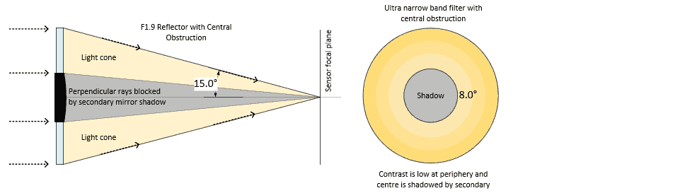
The dark grey area in the diagram represents the “secondary shadow” of a fast reflector such as RASA or Hyperstar. A very narrow FHWM filter designed to be on-target at the increased AOI (yellow area) on such a reflector would show an area of low contrast at the edge of the image. Also, because the centre is effectively blocked out, a greater proportion of high AOI rays are present. Contrast is significantly lowered overall.
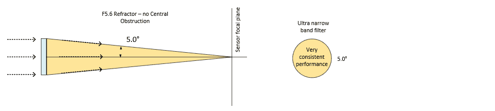
In this example of a slower focal ratio refractor (well actually F5.6 is pretty fast in optical terms!) the light cone contains a mixture of rays of all angles from 0 to 5 degrees, and so filter performance is more consistent over the whole area with higher overall contrast and better transmission.
Generalised conclusions:
- The faster the F-Ratio, the more tilt (increased Angle Of Incidence or AOI).
- Filters with the narrowest bandpass give better contrast than those with wider bandpass at longer focal ratios.
- Filters with the narrowest bandpass will always be more sensitive to tilt, and therefore, on fast focal ratio telescopes they will show lesser contrast than wider bandpass filters.
- At the same focal ratio, fast refractors deliver better contrast with narrowband filters than fast reflectors, seeing they have no central obstruction.
- Ha and Sii wavelengths are the most affected by tilt, while shorter wavelengths such as Oiii and Hydrogen beta are more tolerant of tilt.
- For ultra-fast scopes, especially reflectors with central obstruction, a specially pre-shifted ultra-narrow filter, or wider FWHM filter is your best bet. BUT beware that if too narrow, the centre of the image will lose contrast compared to the edge. In reality, you would require a specially tuned filter to a particular type of optical tube, at a specified focal ratio, with or without a central obstruction.
- F-ratio “speed” has a “price”. If you want high filter efficiency and contrast, F4.8, F5.6 or longer focal ratios usually win on filter efficiency, unless you have a specially “tuned” pre-shifted filter as mentioned in point above.
- Even with a preshifted filter contrast can never be as constant over the whole field as with a filter designed for a slower focal ratio. In fact, a slower focal ratio instrument with central obstruction almost always wins on contrast compared to a fast focal ratio telescope, with or without a filter.