1. How to work out the rough focuser drawtube position with your particular camera setup:
The quad APO astrograph lens system is designed to perform best at infinity focus. This enables it to outperform DSLR lenses costing many times the price, in both resolution and contrast, not requiring the usual compromises required for close focusing.
A proper astrograph focuser is installed with special bearings to improve focusing smoothness and collimation. The focuser drawtube has 29mm of travel, which is intentionally short, compared to many refractors. This is to allow enough space for the focuser drawtube to move back and forth without striking the rear lens element, offering a “range” within which the sensor needs to be placed.
The focuser has two threads for connecting your imaging equipment. These are an M54x0.75mm female thread, and an M48 rear male thread adaptor. These adaptors add space between sensor and lens. Therefore, one needs to ensure that their camera sensor falls within the “range” of the focuser. In some cases, this requires an extension to be added, to ensure your camera sensor is able to reach focus position at infinity. Small adjustments are then made with the focuser.

Altair 70EDQ Focuser Rear M48 thread shown above.
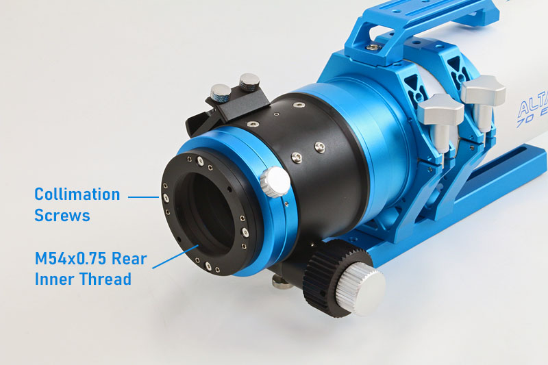
Altair 70EDQ Focuser Rear M54 thread and the position of the Collimation screws.
Seeing the focuser can only be racked out by 29mm, you can check whether your imaging train fits within this limit, and add spacers if it does not.
For example, let us assume you have an imaging train composed of say, an Altair Magnetic filter holder (17mm optical depth) and a Canon EOS DSLR camera (44mm sensor to flange distance) which together take up a total of 61mm in total from the M48 flange on the focuser to sensor. You would subtract 61mm from 69.2mm seeing you are using the M48 adaptor as shown in the diagram. This would then require you to rack the focuser out by 8.2mm to reach infinity focus. You would require the drawtube to be racked out to 14.2mm for a 55mm imaging train, about half-way.
Let’s assume you have a Hypercam TEC cooled camera (with 17.5mm sensor to flange distance), and an Altair Magnetic filter wheel (17mm), you would subtract a total of 34.5mm from 69.2mm, which would mean the focuser is racked out by 34.7mm. HOWEVER the focuser can only be racked out to 29mm, so you would need to add a 5mm extension at least, or, if you prefer the focuser to be racked inwards as much as possible to reduce strain on the drawtube, a 10mm or 20mm extension could be used.
There is plenty of space to use most filter wheels and cameras with the M48 adaptor. However you may also want to use the M54 rear adaptor, in which case you would calculate the drawtube position using 75.2mm as the sensor to M54 focuser rear flange distance, and so-on. This would be useful if you have a full-frame camera and OAG. There is also am M63 rear focuser thread with flange terminating at 87.2mm from the sensor position, however this would require removal of the M54 adaptor with built-in collimation plate, and you would have to use a camera with built-in collimation plate to compensate for any shifting.
Here’s a diagram showing the sensor position for the two rear thread options:
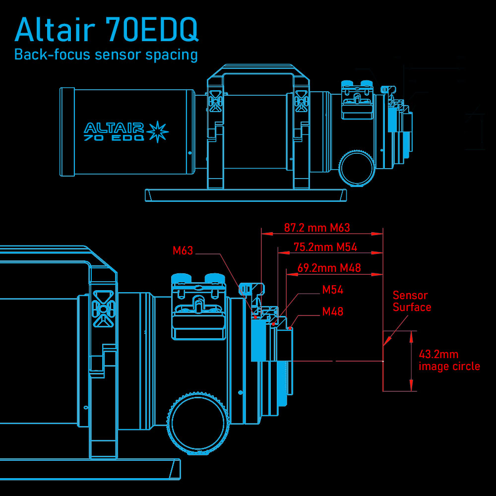
Altair 70 EDQ Quad APO Back Focus Diagram Spacing to Sensor
2. How to collimate your imaging train
Whilst this often isn’t required, provision is made for collimation of the focuser relative to the entire optical, to ensure the camera sensor is orthogonal to the astrograph rear element. Accessories like filter wheels and so-on can introduce slight tilt. In most cases this is taken care of in processing software as the effects are easily compensated for by software. However if your imaging train has sever tilt issues, you can adjust the rear focuser M54 flange to compensate for it. See the above image showing the position of the focuser collimation screws. Collimation is best done with software assistance.
There are four pairs of collimation screws corresponding to each side of the camera sensor, XYZ style. We recommend orientating your camera sensor to the XYZ planes to make collimation easier. To adjust tilt on one axis, you would need to loosen the outer locking grub screws, as well as the larger main collimation screws. Each time an adjustment is made, you would need to compensate for it by loosening or tightening all the larger main screws slightly. When optimum collimation is reached according to your software, you would then tighten up the smaller locking screws each side of the main screw to lock the tilt-plate in it’s new position.